PG Diploma in Piping Design Course
Piping design software is an inevitable part of piping engineering in recent times. Using these piping software packages a piping engineer/designer prepares 3D and 2D models of the exact plant. The exact piping arrangements are produced with exact dimensions, coordinates, and sizes similar to the real plant which helps in actual space estimation, clash checking, pipe routing, and supporting. Abroad, especially in gulf countries, the requirement of piping designer and piping design engineer is huge.
- 25Hrs Course Duration
- Online & Offline

Piping Design Course Syllabus
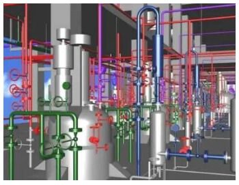
Volume - I EQUIPMENT
PDMS (Plant Design Management System) as it is known in the 3D CAD industry, is a customizable, multi-user and multi-discipline, engineer controlled design software package for engineering, design and construction projects in offshore and onshore.
Volume - II Pipe Work Modelling
Volume - III Structural Work
Volume - IV ELECTRICAL WORKS
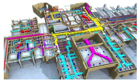
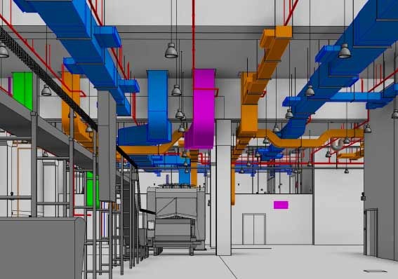
Volume - V HVAC
Volume - VI Hanger & Supports
Volume - VII Report Generation (MTO)
Volume - VIII Spooler & ISO Draft
Volume - IX Drawing Manager
Volume - X PDMS Commands