mechanicaldesign.in

PG Diploma in Piping Design Course

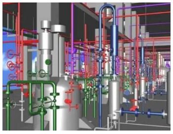
Piping design software is an inevitable part of piping engineering in recent times. Using these piping software packages a piping engineer/designer prepares 3D and 2D models of the exact plant. The exact piping arrangements are produced with exact dimensions, coordinates, and sizes similar to the real plant which helps in actual space estimation, clash checking, pipe routing, and supporting. Abroad, especially in gulf countries, the requirement of piping designer and piping design engineer is huge.

4.5
4.5/5

Piping Design Course Syllabus

Volume - I EQUIPMENT

CHAPTER-01: Introduction about Piping & PDMS, PDMS Login and MDB, PDMS Modules Introduction (like equipment, pipe, structural, hangers & supports, cable tray, HVAC and report, etc…), advance of PDMS design concept, creation of Equipment, primitives & Standard Equipment, Electrical equipment component and cut out Primitives.
How to Create Nozzle, Nozzle Placement, type of Nozzles, Nozzle Orientation, Nozzle Specification Selection and Nozzle class selection, copy of primitive and offset, mirror and rotate
Equipment co-ordination, Position of equipment, create & Modification of list, working with 3D view, using command window, using of Explicitly and Relatively position, basic equipment creation, use of position control tool.
Creation of Standard Equipment in the library file, modify Property of the standard Equipment, Equip
Usage of the Model Editor Tool, edit settings, selection settings, How to use with the Model Editor tool and model editor settings, set the increment of model editor, delete selection and use of wholly / partially within.
Creation Working Plane, Creating deferent shape use with Extrusion primitives And Revolution Primitives, Creating Mitter Bends.
Deals with the general settings, display settings, members, view settings and command window, general query setting

PDMS (Plant Design Management System) as it is known in the 3D CAD industry, is a customizable, multi-user and multi-discipline, engineer controlled design software package for engineering, design and construction projects in offshore and onshore.

Volume - II Pipe Work Modelling

Basic of piping fundamental, create pipe, branch, and piping components, pipe work hierarchy, pipe orientation, connecting pipe, placing pipe, branch replacing, create insulation of pipe, create tracing of piping, material selection of pipe, connect method of pipe.
Pipe creation using explicit method, modification of specification, component Bore/specification, Arrive & Leave, connection reference and slope, Detail plot file, pipe create by model editor, pipe create by command Line Material selection of pipe.
Orientation of component, branch connection, creating pipe assemblies, splitting pipe and pipe isometric drawings system isometric drawings, data consistency error founding and auto pipe router, pipe penetration, show pipe system.
Positioning of branch piping components, maintaining bottom of pipe (BOP), Drag piping, clash checking and pipe work toolbar.

Volume - III Structural Work

Create a Structural hierarchy, how to set default profile for section, set section storage area and node storage area, working plane, plant grid, create a section using straight method, curved method and ring method, regular structure.
How to create tower using regular structure, description about upper &lower S.O.P, bracing configuration and joint creation, base plate creation, foundation creation, 3 leg tower create using grid.
About modification of section elements, creation of fittings and positioning of section, creating brazing gap, Miter ends, Maintain Bracing gap, give the material about creating section.
Section connection, orientation of structure, general settings and grid creation, structure query settings, utilities setting like data checker, reference data, constructs, grid, user grid system at wall ends, position & orientation of wall & floor and connecting wall, Material & Weight Calculation.
Creation of panel, Panel Specification Selection, Extrusion\Panel, negative extrusion, Level Vertical, splitting of panel, positioning of panel and panel fittings & connections and material weight calculation
Creation of wall & floor, modification of wall & floor, Apply Fittings for Walls & Floor, tre and connection at wall ends, position & orientation of wall & floor and connecting wall, Material & Weight Calculation.
Creation of Rectangular, circular, freeform, polygon platform, modification of platform, platform Opening, platform geometry and layout, handrail and deletion of platform & handrail. Creation of Handrail and modify of Handrail.
Creation & modification of stair flight, stair tower, ladder and circular platform @90°, 270°, 110

Volume - IV ELECTRICAL WORKS

Creation & modification of cable tray, positioning of trays and general utilities. Modification of cable tray specification.
Creation modification of cableway, branch elements, route point, route node, route attachment points and material control node, check connection, dressing cable way system. Cable tray support.

Volume - V HVAC

Creating inline plant Equipment like AHU, DUCT Routing, Apply Grid and Tiles on grid, creation of Hvac components, modification of HVAC, positioning of duct, Specification Generator, Auto Fills with straights, surface area & weight and general utilities.

Volume - VI Hanger & Supports

Creation of hangers & supports, modification of hanger, pipe rack, configuration, positioning of support, support plan, Support Relocation, max span, steel profile, Support Axes and general utilities.

Volume - VII Report Generation (MTO)

Report generation (MTO) using template, creation of template modification of report and filter report, pipe & steel MTO, Nozzle & valve schedule preparation, column report, report summary and report format.

Volume - VIII Spooler & ISO Draft

Fabrication Drawing, Advance isometric drawing, creation of spool drawing, field & shop weld creation, spool break and isometric drawing of pipe, modify MTO status, convert to DXF, DWG & DGN.

Volume - IX Drawing Manager

Generating 2D view from 3D view, creation of department, sheet, user defined view, limits defined view, modification of sheet & view, creation of predefined frame. Intelligence text.
Creation of 2d draft, shapes, symbols, text and modification of dynamic primitives, sketch Drafting, Load text, Add Local symbol, Symbol Library Demolish symbol, 3D Representation, DB Listing, Dynamic primitives & Text and general utilities.
Creation of Layers & Layer Definition, create & Modify Labels, Linear & Angle Dimension, Edit Dimension text, Definition of Dimension, Modify of Dimension Colour & Font, projection text, Label definition, Auto Tagging, Auto Drawing Production, Visibility and placement, Define Equipment centre Line and pipe end label.
Section view generation, creation of section flat, section perpendicular, stepped, Detail view, Display 3d view, hatching rules , Schedule and Tagging, Auto Drawing production, Steel Work detailing, Hanger & support Detailing, converting to dwg format and auto drawing production.

Volume - X PDMS Commands

Over all Clash checking, Auto clash, Auto Naming, Hole Management, Associations, Data base export & import, export for other software format, 3D view options, Draw list, Hide file, New Local view section, new clone view, Representation Setting and Auto colour.
Piping Design